Gfci outlet wiring diagram What is the difference between circuit breaker and gfci? Cooper gfci wiring diagram
Eaton GFCI Self-Test 15A -125V Receptacle with Switch with Mid-Size
Gfci wiring outlet diagram electrical wire outlets receptacle house switch schematic light multiple installation problems basic jesse sponsored links Safe to install a gfci receptacle here? instructions have dire warnings Gfci outlet installation instructions
Wiring diagram gfci cooper combo schematic leviton switch
Eaton gfci self-test 15a -125v receptacle with switch with mid-sizeGfci wiring outlet diagram electrical outlets circuit pdf installation schematic switch 55kb buildmyowncabin instructions wire receptacle ensure diagrams light basic What is a gfci and where is it required?Gfci receptacle cables dire warnings wires.
Gfci outlet wiring breaker difference afci electricaltechnology connectedGfci wiring diagram circuit receptacle connected terminals ordinary Eaton gfci hubbell receptacleGfci receptacle nec eaton.
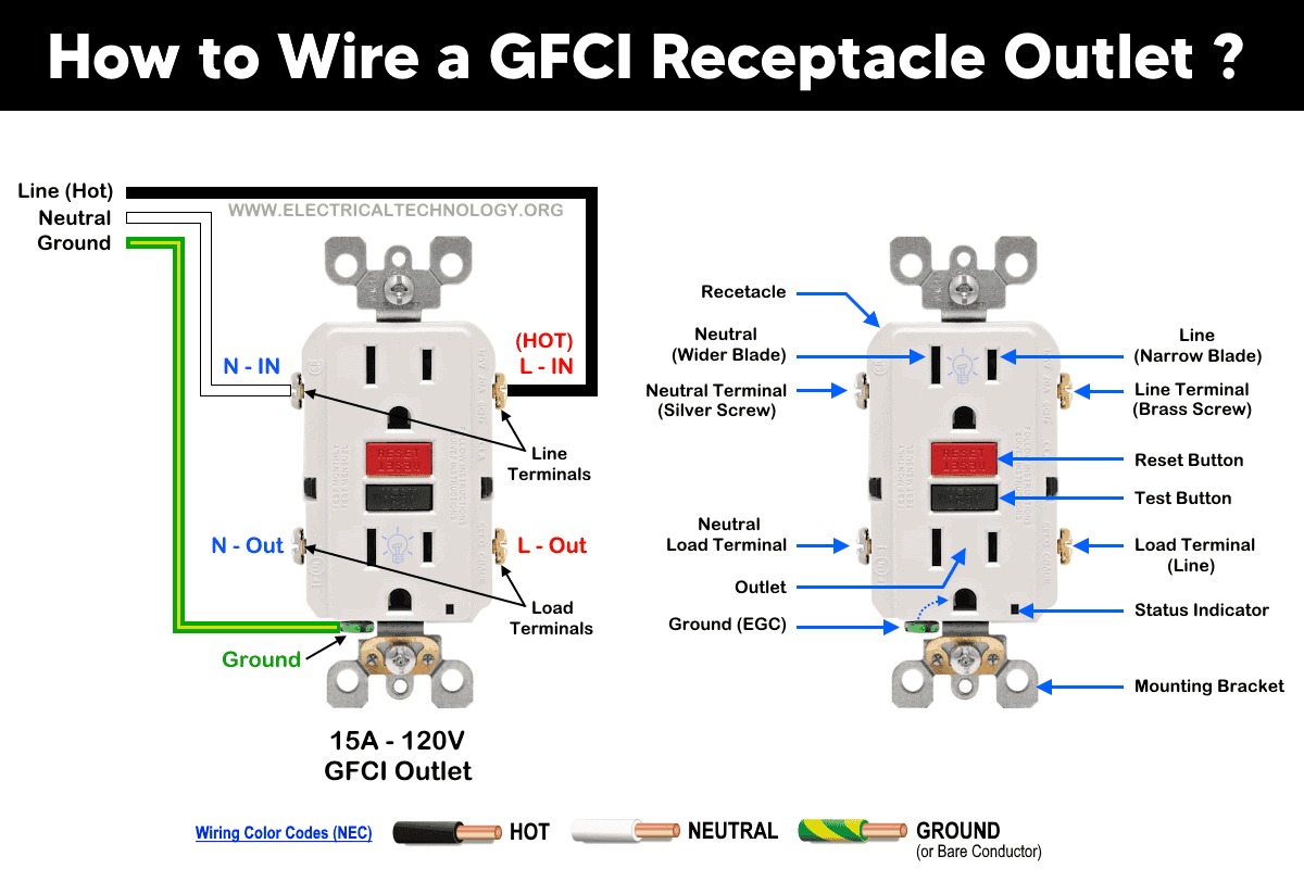
How to wire a gfci outlet?
.
.

Eaton GFCI Self-Test 15A -125V Receptacle with Switch with Mid-Size

How to wire a GFCI Outlet? - GFCI Wiring Circuit Diagrams

Safe to install a GFCI receptacle here? Instructions have dire warnings

Cooper Gfci Wiring Diagram

What is a GFCI and where is it required?
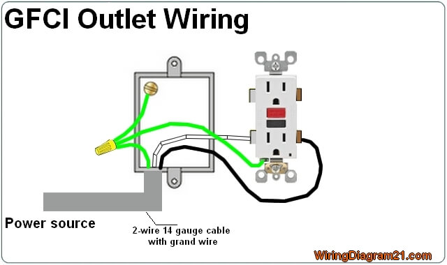
GFCI Outlet Wiring Diagram | House Electrical Wiring Diagram

